My UAG is Down!

Hi folks. Worked a case with a customer recently for a pair of UAG v.2103 servers that were down. Both were pingable, but neither were serving clients and the administrators could not get to the Management Interface (port 9443). They had already rebooted them a couple of times to try and get it back in service. It was noteworthy that their UAG1 went down and the load balancer shifted the traffic to UAG2, but UAG2 failed about 2 hours later.

I hopped on to a zoom session with our customer and got a Webconsole session to the UAG1 appliance.

First check, ran: netstat -ano and noted there were no listeners for ports 443, 6443 or 9443; so it was pretty much dead in the water. Fortunately, the customer was running a pair of UAG’s with a load balancer in front – so business wasn’t impacted (they had less than 1000 Horizon users).

After continuing basic troubleshooting the answer came in the form of: df -h . The volume \dev\sda2 was at 100% and killed the system. Checking through the filesystem for large files – we found it in \var\log. Auth.log had grown to 6.8GB and filled up the root partition. Once that happens, several things will be seen:
– Services will start failing (including services for UAG).
– System logging facilities will fail (due to no space to write logs)
– Possible system/services corruption if a critical file/configuration file was in the process of being written to disk when the partition became full.

All three are ‘bad things’ in the IT world.

The Initial Fix:
So, the short term fixup is to clear out space on the file system. In this situation, it was the auth.log file that was taking up all the free space. This service (and consequential logging) is for tracking system authorization information, including user logins and authentication mechanism that was used. This includes authorizing local users via PAM, sudo and also onboard processes that use service accounts on the system. On inspection of the file, there are 3 entries for every authorization tracking, so if there’s a lot going on with your UAG, it can grow over time. In this instance, the UAG had accumulated 6.8GB of logging in 8 months – that’s a lot of logging.
I wasn’t sure if the customer had an auditing requirement in place, but figured it would be safer to copy out the file instead of just killing it. After using WinSCP to copy the file out of the partition, we then ran: truncate -s 0 auth.log to “zero” out the file without deleting the actual file name, so actual file permissions would remain unchanged.

Still Not Working:
After clearing out the space and rebooting, the system came back up and we had a console to look at in vCenter, but services still weren’t showing up. Back to the commandline.

We verified that there was plenty of free space on the system now and then ran: netstat -ano again, and noted that none of the listener services were up and running (ports 443, 8443, etc). We then headed to the system logs to discover what is failing us here.

The answer was in \var\log\messages where there were numerous startup errors with Java configuration files (I didn’t get a snapshot of those to share). Java is the engine that runs GUI interface that clients connect to inside of UAG, so if Java ain’t happy – nobody’s happy!
Fortunately, the customer had a recent backup of the UAG from a couple of days back, so trying to figure out how to fix a Java configuration and likely a file corruption issue wasn’t an issue. They did a restore of the prior UAG and a little reconfiguration of their environment, they were back up and running again. We walked back through the truncation of the auth.log file to ensure that it wouldn’t crash again in a couple of days. They then ran through the same process on the 2nd UAG server to get the environment back to full redundancy.

Long Term Fix:
I pulled the logs for a review of what could be spamming the auth.log, but everything looked like valid entries. Nothing generating excessive or concerning authentications, just a UAG doing it’s business. So from that, it would seem like this file should’ve been included in standard log rotation via a CRON job or something to manage the storage space better. It’s possible that VMWare may have excluded this file from log rotation due to a ‘best practice’ for auditing, where you do not delete log entries that would indicate or could trace a compromise _by default_, make the Administrator or Audit team clear the logs by intent to preserve any potential evidence.
In our case, the customer was ok with adding the auth.log file to the standard CRON job log rotations.

So, some key takeaways from this event:
– True backups (not snapshots) of your infrastructure are a fantastic fall-back position!!
– Horizon admins that use UAG, check in on your free space occasionally!!

Questions/comments are always welcome here.
Hope this helps!

How to Skip Learning vi Editor

I got to learn basic vi/vim editor the hard way many years ago reviewing Cisco PIX firewall logs and setting up jailed FTP sites on SuSE linux, so I’m in the cool club. But there are tasks that I sometimes need to do on larger files that become a bit of a pain to look up “how to do xxxx in vi” for 2 seconds of IT Glory – and then promptly forget how to do it till you have to look it up again…

Enter the cheatcode: WinSCP.

WinSCP is pretty well known for being able to do secure file copy using SSH/FTPS between Windows and Linux/SSH capable computer systems. What some may not know is that it can invoke Windows Notepad or use it’s own Internal Editor to edit files on the remote system. So, instead of using an SSH client, like puTTY, and clumsily fumble around with vi/vim to enable edit mode, make sure your emulation is correct, make changes without hitting the backspace key and remember the keystrokes to write/save/quit (seen below), you can use a much more friendly GUI text editor to get your work done!

Here’s what vi looks like via puTTY session. Not very descriptive, unless you have a vi User’s Guide handy and have some time on your hands to get all the commands right.

Leveraging WinSCP for text file viewing/editing is pretty simple, let’s walk through this.

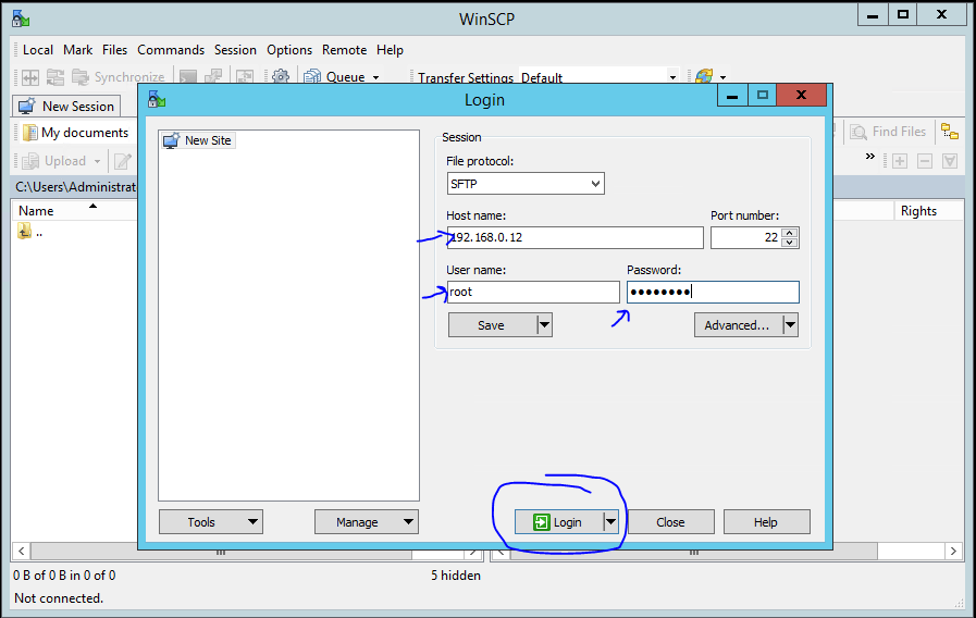
1. First thing (after installing WinSCP) is connecting to a system that has SSH already enabled. Start up WinSCP and it’ll prompt you for what system you want to connect to. Just type in the IP address or FQDN of the system, User Name and Password, then “Login”, very similar to puTTY.

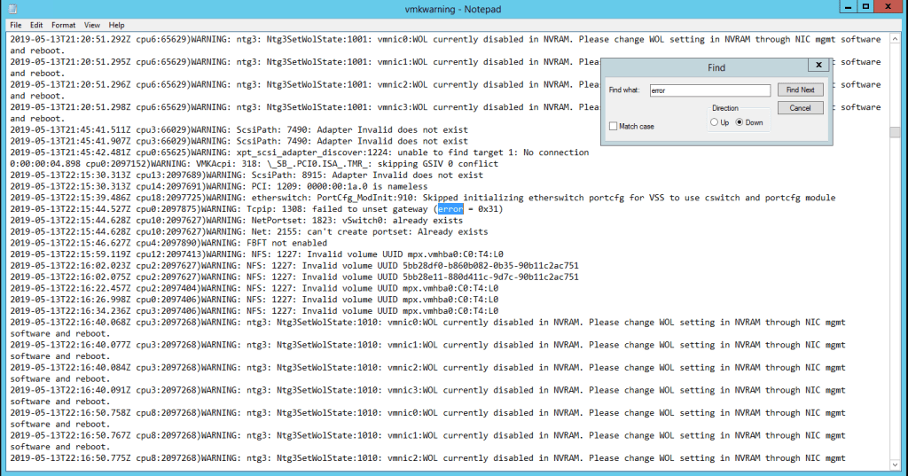
2. Your local file system will be displayed on the left side of the window, but our item of interest is on the right side of the window – the remote file system. With the Commander-type interface, you can navigate very easily without a lot of ‘cd’, ‘ls’ and ‘cd ..’ commands in puTTY to get around the file system. The target system I connected to is a VMWare ESXi host and I want to check out ‘\var\log\vmkwarning.log’ file to look for errors.

Just like in Windows, you double-click on the folders to navigate down the folder structure. Once we’re at \var\log folder, scroll down to find ‘vmkwarning.log’ and right-click on it. There several file operations you can do on the file including download to your system, duplicate the file on the remote file system (like a backup copy) and you can Edit the file using Notepad or the Internal Editor that comes with WinSCP. For our example, we’ll use good ol’ Notepad to do our log review.

Once opened, it works just like a windows hosted text document and in a quite familiar and useable GUI interface where you can scroll around, use your mouse and do searches for key words. Let’s look for the phrase ‘error’ to see what we find.

Aside from doing finds, you have the whole toolbelt of Notepad features to use on files: search/replace, cut/copy/paste, etc.

How to Make & Save changes

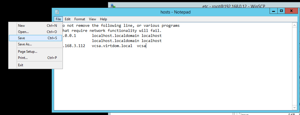
Along with doing log review, we can also make edits to files and save them back to the remote system. For instance, we need to make an edit to the hosts file on a system to hard-set an IP to FQDN mapping (in case DNS has failed or isn’t reliably reachable). Just change or add the information needed in the file and then hit “File : Save” to save the changes back on the remote host. Just that simple!

I hope this has been helpful for those that are vi challenged, or just don’t know anything about vi editor. Many of my customers that are new to VMWare and Linux are surprised & pleased to learn about this workaround.

Comments??

VMWare Horizon: Internal Error Occurred – How FLEX console saved us.

Hey folks. Again, it’s been a while since I’ve posted up something here, but I found something recently that was worth sharing. A customer ran into an issue while running Horizon 7.12 and trying to do a Recompose on the Pool.

Background: The customer had installed Horizon 7.12 and created a pool of GPU enabled desktops using nVidia GRID. Unfortunately, after a 2 month deployment, he found that the virtual desktops (VDs) were experiencing lag, screen artifacts and overall slowness. The admin did some research and found some more optimal settings for the pool (not going to discuss the changes here) to “allocate all memory” for the VD pool to help with the video processing. After making changes to the base image and taking a snapshot, when the admin kicked off the Recompose on the pool, he got a very vague “An Internal Error Occurred” and that was it. No useful errors in the vCenter or Horizon console at all. Recompose on the pool was just failing.

Troubleshooting: What’s the first thing you do in this situation? Pull a log bundle on Horizon and find the problem!! Well, that’s what we did – having the customer timestamp when the Recompose failed and relay that along with the LogBundle for review. Digging through the logs, there was nothing obvious failing here. Going to my favorite “needle in a haystack” analysis style, I pulled up BareGrep and started doing targeted grepping of the log bundle for “fail”, “error”, “internal error”, etc.. Something I came up with in a Debug log was a _literally_ cryptic message (highlighted in red):

2020-10-30T15:13:49.440-05:00 TRACE (2564-1EF8) [Event] Raising windows event ([VLSI_DESKTOP_RECOMPOSE_FAILED] “domain.org\username failed to request a recompose of 99 machine(s) in desktop Graphics users no video card. Full Adobe Suite”: Node=server.domain.org, DesktopId=graphicsusers, Severity=AUDIT_FAIL, Time=Fri Oct 30 15:13:49 CDT 2020, MachinesCount=99, ViewAPIDesktopId=Desktop/Yjg3YTVlNTYtNTVhMy00YWIxLTkyOTEtMTc3YjAxMThmOTZl/Z3JhcGhpY3N1c2Vycw, DesktopDisplayName=Graphics users no video card. Full Adobe Suite, Source=com.vmware.vdi.vlsi.server.resources.DesktopViewComposerManager, UserSID=########, Module=Vlsi, UserDisplayName=#####.###\######, Acknowledged=true)
2020-10-30T15:13:49.440-05:00 ERROR (2564-2210) [RestApiServlet] Unexpected fault:(vdi.fault.EntityNotFound) {
errorMessage = BaseImageVm does not exist on VC VirtualCenter/Yjg3YTVlNTYtNTVhMy00YWIxLTkyOTEtMTc3YjAxMThmOTZl/MjY3NzJkN2QtODBkYi00OWI1LTkxMmMtMTM0MDNjZTY1OGEw,
id = (vdi.EntityId) {
dynamicType = null,
dynamicProperty = null,
id = BaseImageVm/Yjg3YTVlNTYtNTVhMy00YWIxLTkyOTEtMTc3YjAxMThmOTZl/MjY3NzJkN2QtODBkYi00OWI1LTkxMmMtMTM0MDNjZTY1OGEw/L0RhdGFjZW50ZXIvdm0vVkRJIC0gR3JhcGhpY3M/dm0tMTA5
}
} for uri /view-vlsi/rest/v1/desktop/recompose

Obviously, the internals of Horizon was hashing the name of the BaseImage, so we really couldn’t figure what it was trying to look for here (although just the error message was a clue here – keep reading). After chatting with a colleague at VMWare, it was noted that we were using the HTML5 interface for Horizon management (as you should these days) and that we might be able to get more information by doing the Recompose in the FLEX interface. Although FLEX is going away, it still has some features and reporting/feedback that is not in the HTML5 interface yet. Per my source, FLEX was deprecated in ESXi 7.0 as the HTML5 interface has been built out well enough to be the only management interface for ESXi and vCenter. However, other products HTML5 management consoles are still being developed, specifically Horizon. So, as long as your version of Horizon shipped with a FLEX console, you will have access to use that alternate console.

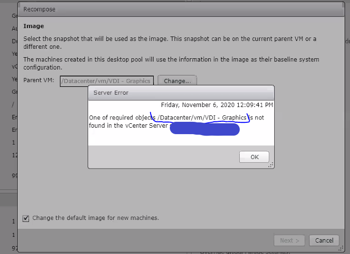
So, bringing up the FLEX console and walking through a Recompose function got us some additional information! Take a look:

That file reference is clue #2 of the puzzle – we now know what file the Recompose is looking for. We drilled in to vCenter (blacked out) to verify that the VM is there, and sure enough, under “VMs & Templates” it was located at \DataCenter\vSAN\VDI-Graphics. But that still didn’t look right…
On a hunch, I asked the customer to clear the error and let’s use the “Change/Browse” button on the “Parent VM” field (in the background). Once we did that, we found the problem. In the pop-up for locating the Parent VM, we were presented with “/Datacenter/vm/Parent/…” folder structure, where all the Parent VM’s were located – not “/Datacenter/vm/…”
Apparently, some process or some one, had moved the Parent VM’s down one level, consequently breaking all Pool Recompose operations unless the Parent VM field was repointed to the new location.

Once we re-pointed to the new location of the Parent VM, the Recompose process went off without a hitch!! The customer went back and checked the config of other pools and found they were affected with this issue as well. Fortunately, you can re-point in either the HTML5 or FLEX interfaces, but this error wasn’t handled well in the HTML5 console. Apparently, the HTMT5 console is still a work in progress, so when you run into Error conditions that aren’t explained well – give the FLEX console a shot!

Hope this helps.

Taking A Look at the nVidia T4 GPU

Hey folks,

It’s been a little while, but with the current status of the world I had some time to play with some new toys at work.  I just got my hands on a Dell R640, with a configuration on it to do VMWare vSAN and Horizon with GPU.  Acutally, the order was for 3 R640’s, with dual socket (12core/socket), 96GB of memory, 6x600GB SSD and a T4 GPU.  I’ve been keeping in the loop of GPU’s and VDI for some time now – about 8 years back to the nVidia K-cards, but I have been retooling to master VMware OS platforms – so I haven’t been too “close” to the hardware side of things.  Fortunately, it was time for an upgrade for some lab hardware, as the older 12th Gen Dell servers I have are not supported on VMWare vSphere 7 (which just dropped 4 days ago).

Anyway, we can’t just go out and buy _the_ latest and greatest hardware that hits the marketplace, so the T4 is a nice place to start…  I did a quick video on the T4 & Dell PowerEdge R640 and posted it up on my YouTube channel here:  https://www.youtube.com/watch?v=pxafUlgpWDg

As I get this stuff setup in the lab, I’ll make up some new articles and maybe some more videos to demo this stuff out for y’all.  Please feel free to throw comments/questions below.

Thanks, Scott

How to Recover “Bricked” Teradici endpoint on Wyse P25/45, Dell 5030/7030

Hey folks!  I recently had the opportunity to play with a P25 that had been on the shelf for quite a long time (like – years..).  The unit either had a very old version of firmware on it, or someone had been experimenting on it and had it back-flashed to Firmware 4.0.
Either way, it needed to be updated for a class I was teaching.
So, plunging into the task, I did the standard process:

  1. Download the latest firmware package to my local workstation from Dell Drivers & Downloads (http://support.dell.com  & enter the service tag)
  2. Discover the IP address of the Endpoint through the On Screen configuration.
  3. Open a browser and navigate to the IP address of the Endpoint.
  4. Log into the Administrator Web Interface (AWI) and I went to Upload and proceeded to update the firmware to v.5.3.0.

However, on reboot of the system, it appeared to have “bricked” the endpoint.  There was no display, although the power button was lit up and the unit was on.

Stepping through basic troubleshooting, I noted that the NIC interface (RJ45) was showing a link light.  Even with the display not working, I went to DHCP to see if it had registered an IP Lease recently & fortunately, it had!!

Heading to the AWI on the P25, I was able to connect and log on to the AWI.  Checking the configuration on the home screen – it showed that it was actually up and running FW5.3.0.  What give??

That’s where reading the documentation/Readme.txt files comes in handy!!

After reviewing the release notes for multiple versions of the Teradici Firmware , I found that there are “Stepping” requirements when upgrading Teradici Firmware Prior to 4.5.1.  Apparently, there are some video driver updates in 4.5.1/4.6.0 that newer versions of the firmware depend on (meaning they aren’t in the Firmware Updates in the newer packages).

Once I back-rev’d the firmware to 4.6.0, I got the video back up and working.

This is also another “Stepping” requirement to get to FW 5.3.0, there are required components in the 4.7.x & 4.8.0 firmware that update the management plugins for PCoIP Management Console 2.0 to be able to manage the endpoint.

So basically, if you are on a pre-4.5.1 firmware:

  • Update to 4.6.0  to fix video
  • Update to 4.8.0  to fix PCoIP managment bits
  • Update to 5.3.0 & beyond!!

The Release Notes link above should be updated for future revsions of the firmware as they come out.

Hope this helps.

Installing Tera 2220/2240 in Dell Precision Tower System, and How an Install Went Wrong.

Hey folks, it’s been a little while since I’ve posted and time for some fresh content here.  This comes from a recent customer I worked with that had a very strange performance problem with a system they recently purchased.  The customer had ordered a couple of  Dell Precision T5820 systems with an nVidia GTX1080 and Tera2240 card and they were using some older Wyse P25 endpoints for remote workstation access (a pretty nice setup for doing remote graphics).

The initial problem called in on was that one of the systems would lose its CMOS Time when the system was started up remotely from the P25.  Specifically, when the customer would turn on the workstation from the front power button of the Tower – everything was fine, but when the “power on” was sent remotely from the P25, the system would power on and stop pre-POST with the message “CMOS Time not set, Press F1/F2 to continue” – which everyone knows means the CMOS either got reset or lost it’s time configuration… but in this use case, why??

What is a Teradici Card?

A Teradici Host Access card is a pretty impressive widget for doing HD graphics (CAD, design, modeling) from a remote location.  The HAC can accept input HD Video from an onboard video card, scrape 6 different functions off the motherboard via the PCI bus (keyboard, mouse, audio and several USB device channels), then compress and packetize all of those to send across your network to a hardware or software client with almost lossless video.  This provides the end user access to a high quality user experience while the system stays secure at the office or in a datacenter (meaning: the data stays secured).

One additional cool feature of the Teradici Host Access Card (HAC, from here forward) is that you can remotely power up/down a system that has a Tera card installed.  This is accomplished on the HAC through a 2-wire, power management cable that connects a jumper on the HAC to the Remote Power jumpers on the motherboard of the system where the HAC is installed (picture below).

Tera_PowerMgmt_Cable2

Installation:

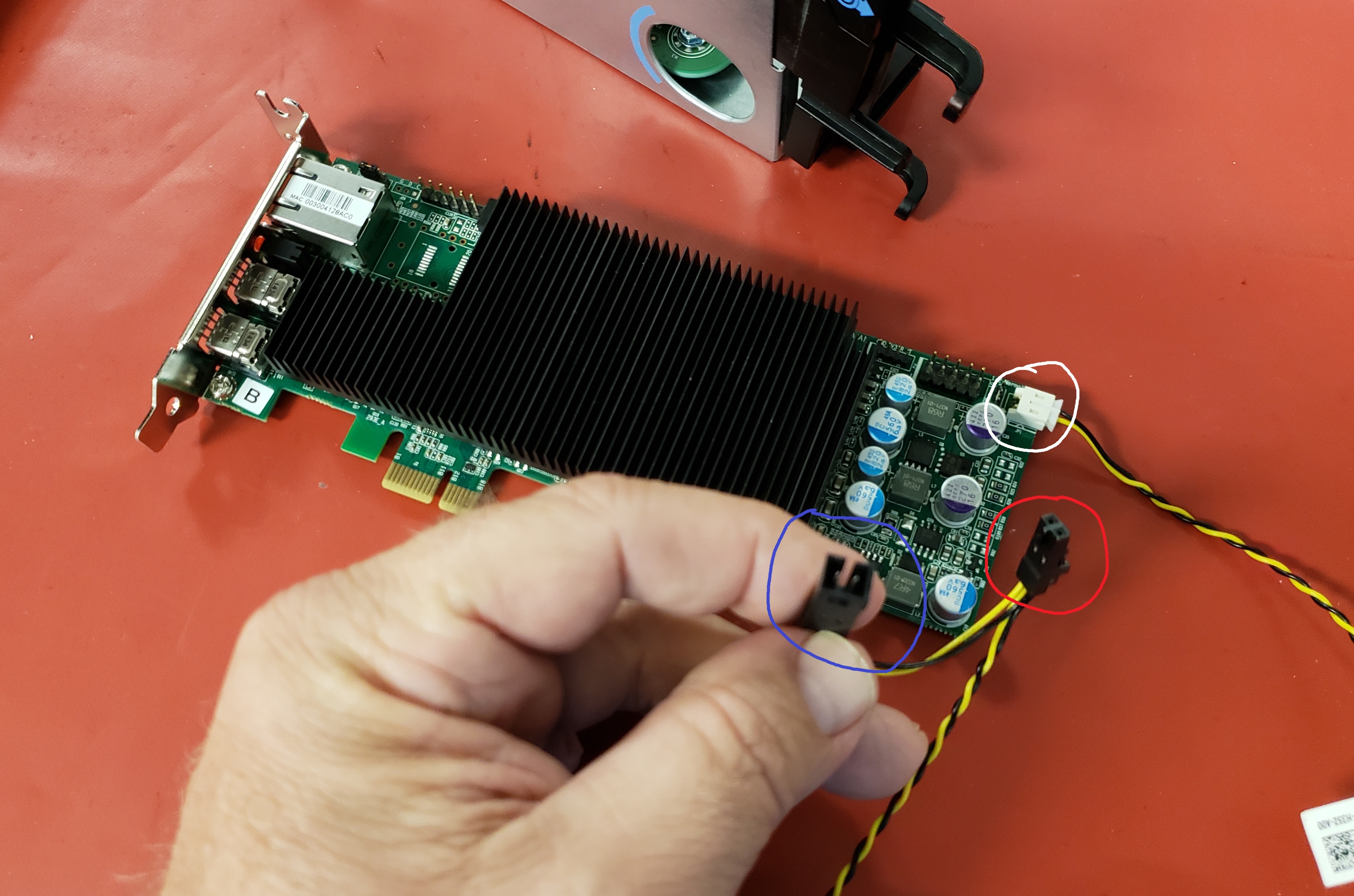
The picture above is a Tera2220 with Power Managment Cable attached to the card (white socket/circle).  It’s a standard PCIe device and just plugs into a PCI slot in your system.  If you have a dual socket system and only have one socket populated, check your motherboard documentation on which PCI slots are driven by the installed processor.  If you happen to be in that scenario and plug it into a PCI slot that belongs to the empty 2nd socket, the HAC will power up (it pulls power through the PCI slot) and you will be able to access the WebInterface for the device (AWI), but it won’t be able to interact with the system (mouse/keyboard) because there’s no processor handling the I/O from that PCI slot.  This scenario isn’t an uncommon problem and we’ve diagnosed it quite a few times.

Once installed in the PCI slot, there is also the Power Management Cable (PMC) to deal with.  One end of the PMC should already be attached to the HAC.  At the other end is what equates to a “splitter”.  The power management cable can be used on systems with a Remote Power jumper on the motherboard, or on systems that only have a single  power control jumper for the bezel mounted Power Switch.  The port circled in red above is the connector that will be plugged into the Remote Power socket on the motherboard.  The connector I’m holding (blue circle) is only used if you do not have the 2nd Remote Power jumper on your motherboard.  In that instance, you will unplug the the bezel power cable plugged into the motherboard jumpers and plug the bezel power cable into the socket I’m holding, then plug the red circled connector into the power jumpers on the motherboard.

After that, use the supplied DisplayPort to miniDP cables to jumper the video out from your HD Graphics card into the Teradici HAC.

That’s it for installation.  As long as you know where the Remote Power socket _is_ on the motherboard…

The Fail part…

After a lot of remote troubleshooting of the System, checking BIOS, sending a CMOS battery, Tera HAC configuration and other checks which I won’t bore you with, we got down to asking the customer for a picture of the area around the PCIe slots where the HAC was plugged in to see how “what is plugged in to where”.

Once we got the picture of the motherboard, the picture became much clearer (all pun intended).  Unfortunately, the only obvious jumpers exposed anywhere near the PCIe slots on the T5820 were:  BIOS Password Reset & CMOS reset.  The BIOS Password Reset jumpers are covered/jumpered by default on Dell systems and the CMOS jumpers were the only uncovered jumpers available (in the Red Circle below).

Somehow, some way, the Tera card’s Power Mgmt Cable had been plugged into the CMOS reset jumpers.  So when they executed a remote power command from the P25, the Tera card was closing (read as:  jumpering) the CMOS Reset and wiping the configuration.  This explains how the front Bezel power-on didn’t exhibit the issue when used, but would wipe the config when doing power control from the Wyse P25.

Fortunately, the correct jumper socket for Remote Power was found next to all the Bezel control jumpers at the opposite edge of the motherboard from the PCI slots (noted by blue arrow, below), hidden under all the cables for the Bezel controls (and the socket wasn’t labeled either – that detail was pushed back to Engineering).

T5820_PCISlot_area_1

Once the Power Mgmt Cable was tapped into the Remote Power control socket, the system started working as expected.

Have y’all seen any odd outcomes from what would seem like a routine card installation??  Let me know in the comments…

Extra Resources:
Teradici Installation Instructions

Finding/Setting IP address on Teradici

RDS 2016 & 2019 in a Workgroup or With Active Directory – Licensing Failure

** Update 10/4/2018 –  I just tested out RDS installation on Server 2019 in workgroup mode and the same configuration issues will be experienced and the process below will get you through it.  -Scott **

Ok, so if you are here – you already know this is not a recommended configuration for Remote Desktop Services, but you want to do it anyway.  With my experience in Technical Support with a now very large computer company, your odds of succeeding in this endeavor if things go wrong are about 50/50, but let’s get you some info to assist and get you the best odds of winning.

Remote Desktop Services (RDS) is designed to be in a Microsoft Active Directory integrated environment, meaning there is a writable DNS server in the environment and an AD User/Service database to pull environment information from.  Along with the needed AD pieces, there is also the issue of the RD Connection Broker service won’t install, due to the lack of permissions – which means you do not have an RD Management interface with which you can configure your RD environment.  So given these fail points, without taking other steps you will wind up with an RD environment that cannot be accessed due to RD Licensing configuration failure (yeah, you do need RD licenses, too).

Here’s what you will see in EventViewer:System logs:

And when you go to RD Licensing Diagnoser, you’ll see this:

Licensing mode for RDS Host server is not configured resized 600

And looking in RD Overview in Server Manager, you get:

[clip_image00263.jpg]

Since you don’t have the GUI to work with to configure RD Licensing with, we’re going to have to go about this differently.

** Also, if you installed RDS on a system with Active Directory installed, you may, or may not, get the Overview GUI installed on your server (error pic above).  Even if you do have the GUI installed in this scenario – it’s almost a 100% chance that the Licensing Configuration through the GUI will not work.  The tweeks below work to fix RD Licensing for both Workgroup and AD scenarios.


Open up Regedit and navigate to: HKLM\Software\Policies\Microsoft\WindowsNT\TerminalServices

You’ll need to add two keys:

  • LicenseServers  (string value), with a value of your FQDN of the License Server instance.  One option instead of using a FQDN is just use “localhost” or “127.0.0.1” to point the RDS instance to look on the workgroup server for the RD Licensing Instance (as long as RD Licensing is on the same workgroup system).
    • **edited/added the loopback IP address here 2/6/19**
  • LicensingMode  (32-bit DWord), with one of 2 values:  2 – for Per Device mode  or 4 – for Per User mode

Once you have those set, restart the RD Licensing Service and RD Session Host Service and then re-run the RD License Diagnoser – it should run clean now.

** Other important note here…  An RD Licensing instance can handle Per User and Per Device licenses and hand them out with no problem to multiple RD Session Hosts, but a single RD Session Host can only ask for 1 type of RD License – either Per User or Per Device.  This is a common issue where Per User licenses are purchased and installed, but the Default licensing mode configuration for RDSH is “Per Device”.  So, RD will hit your RD license host and ask for a Per Device licenses, which it doesn’t have.  Changing the licensing mode to “Per User” fixes the issue.

Good lucks out there!  Comments??

Wyse Mangement Suite & Blast Deployment

Hey folks, it’s been a little while since I’ve shared something.  But this afternoon I found something worthy.

A customer has some Wyse 3040’s (ThinOS) already deployed, connecting to Horizon View 7.3 on the back end, and now they want to test performance with the Blast protocol instead of PCoIP.  The customer is using Wyse Management Suite to configure their endpoints and is using only 1 endpoint to test with.

How to do this???

The customer is using ThinOS 8.5_012 on their endpoints, but the process is pretty much the same for most WMS/ThinOS clients that support Horizon View.

First, the endpoint needs an additional package deployed to support Blast Protocol.  In ThinOS, the Horizon View Client only supports RDP & PCoIP protocols and manual configuration will only display those protocols in the drop down menu.

If you are using On Premise WMS (locally hosted):

  1. Navigate to where you unpacked your downloaded ThinOS package.
  2. Drill into the PKG folder and locate:  horizon.i386.pkg
  3. Copy that file to your repository on the server that is hosting WMS (..\WMS\LocalRepo\repository\thinClientApps)
  4. Wait a few minutes for WMS to update it’s inventory.
  5. Go to App & Data on the top toolbar & on the Lefthand side:  App Policies – Thin Client.
  6. Create a policy to deliver the new package to the endpoint & confirm the installation by checking SystemTools:Packages and verify that Horizon.i386.pkg is installed.

If you are using Cloud Based WMS, the packages for your ThinOS should already be listed and available.

Once that is done, then just deploy your configuration policy to the endpoint device groups and test.

Hope this helps.

VDI in the College Campus, a Success Story.

Any good VDI Techie knows that College computer labs and VDI were made for each other.  Before XenDesktop & Horizon View took over the leading roles in “We Do VDI Better” in the last three years, there were plenty of computer labs using Remote Desktop services and VDI-in-a-Box.  And before that, Active Directory attached PC’s with some well documented re-imaging process for those times when “somebody did something and now it doesn’t work”.  As times have changed and needs for protecting data have increased, offering accessible computing resources to College students (BYOD or not) have also increased, and a robust solution computing solution for campus environments has always been just out of reach.  Until recently….

The University of Arkansas was recently awarded this year’s Tech Target’s Access Innovation Award for their implementation of a campus-wide accessible VDI based end-user computing project.  The University of Arkansas partnered with DellEMC and leveraged their VDI Complete Solution – a package of VMware vSAN HCI solution, VMWare Horizon View, nVidia GPUs, DellWyse Thin clients & Industry proven PowerEdge R730 servers.  DellEMC was able to provide a sturdy, high performance solution (in computing and graphics processing) to cover 27,000 students on the Fayetteville, AR campus through Lab accessed resources and “roaming” access through campus WiFi and off-campus access.

—————————————————————————————————————————–

Dell EMC congratulates the  University of Arkansas for winning the Access Innovation Award. If you are interested in learning more about how VDI Complete is making high-quality, speedy VDI deployments possible for institutions and organizations across the country,  visit https://experience-vmware.com/vdicomplete/.

CAD Graphics Solution – Converting DVI to DisplayPort

Hi folks,

I recently worked a case with a customer who was setting up a dedicated remote graphics workstation leveraging a Teradici Host Access card for remote access.  The problem they were experiencing was the DellWyse 7030 was connecting to the Teradici card, but they were getting a message “No Signal”.

Here’s the hardware setup:

I had never seen a Quadro K6000 yet, so just to figure out the “lay of the land” the customer sent us a picture of the back of the server – with the Tera card and Video card and current cabling.  The K6000 is kinda unique, aside from having over 2000 cuda cores for graphics processing and using a single-PCIe and two slots wide.  That’s all pretty cool, but the uniqueness is that it has 4 video out ports on the back and it’s made for single user/client video.

However, there’s a problem with the configuration of the 4 ports that can cause some issues when trying to leverage a Tera2240 card.  The K6000 has 2x DisplayPort outputs and 2x DVI outputs, and that’s a problem when trying to light up 4x miniDisplayPort connections to feed 4 monitors on the 7030 endpoint.

The Tera2240 is designed to work with DisplayPort connections only, so it’s packaged with 4x DisplayPort to miniDisplayPort cables to do the Interconnection between the video source (DisplayPort) to the Tera card (miniDisplayPort).

Initially, the customer had configured the solution as in the picture below.  The DisplayPorts on the K6000 are shaded in the picture, but I highlighted them with the Blue circle (there’s a better pic further down), but note that they are unused.

IMG_1207-2

From the image above, the customer had purchased two consumer grade miniDisplayPort (mDP) to DVI adapters to make the connection between the DVI output on the K6000 and the mDP input on the Tera2240.  It seems like it should work because there’s a DVI port on one side and mDP on the other side, right??

Not understanding the solution, they wired it up as above and didn’t understand why it didn’t work and they were getting a “No Signal” message after connecting to the Tera card from the DellWyse 7030.

Let’s break down the parts in the solution real quick, which will help us understand how to put it together and be able to get proper video to the endpoint:

Quadro K6000:  The Quadro K6000 does have 4 video out ports – 2x DP & 2x DVI.  However, there is “precedence” in the default video ports as seen in the host operating system, as to which port has Monitor1, Monitor2,…, Monitor4 video out.  This can be changed inside the OS, but the default is best described by a picture.  Ports indicated as 1 & 2 are your DisplayPort outputs, 3 & 4 are your DVI outputs.

K6000-ports

Tera2240:  As shown below, the Tera2240 card has 4 mDP inputs and are labeled in order.  So, this is just as simple as matching up Video Out ports (from K6000 above) to the Tera2240 mDP inputs in the image below, right??

Tera2240

Well… no.  There’s still a problem – with the converters.

Converters:  After doing some research on video signaling and conversion from DP->DVI and DVI->DP, these are two very different processes.  DisplayPort is a much newer and robust digital video & data transfer interface (go to market ~2008) and is backwards compatible with VGA, DVI and HDMI displays formats.  This is accomplished with a simple passive (read as:  non-powered) adapter that takes the DP signal stream input and strips out everything but the needed signal (based on the adapter output type) and putting it out on the other side of the adapter.  Unfortunately, up-converting from VGA/DVI/HDMI to DP takes a bit more work from a processing side and requires a power input to assist with the computational processing.

So it is important to know what your video source is and what your output is supposed to be and that you get the right adapter for it.


So, putting all of these pieces together, here is what the configuration should look like to provide a Quad Monitor experience leveraging the K6000, Tera2240 & have the video come out properly on the Dell Wyse 7030 Endpoint.

  • K6000 ports 1 & 2 will use the provided DisplayPort to mDisplayPort cables (noted in blue) to connect into ports 1 & 2 on the Tera card.
  • Ports 3 & 4 will use a short DVI cable out (noted in red), which will need to plug into an Active/powered DVI –> mDP up-converter (noted in tan) to translate the DVI signal into a DP capable signal, plugging into ports 3 & 4 on the Tera card, with likely an assist from USB power off the back of the server to power the Active up-converter.

Setup2

Here’s a look at some examples of Active Up-converters to go from DVI–>mDP :
Here…   and…   Here…   off of Amazon.com  (Disclaimer:  I’m not necessarily recommending either of these, they are just examples.  Verify with the vendor that it will work or they have an equitable return policy)

There’s a lot of good info on the DisplayPort spec: here.

Hope this helps.  Hit me with questions.